Saturday, November 17, 2012

Adding 2" to inner wheel houses


July-Sept, 2012
Cut and fab minitubs.      Based on the tire size that I want in the rear of this car there needed to be some work done to the wheel houses.   At the moment I am looking in the size range of 305x45x18 or about a 12” wide by 27” tall tire.    Somewhere in that zone anyway.    We took a picture with a 31” tall truck tire crammed inside the wheel well, and I do believe it is a little too much tire.   J
The first thing I did was to cut out the inner wheel houses so I could weld in two extra inches, taking the wheel house all the way back to the rear frame rail.  Yes, there are companies that sell pre-fabbed oversize inner wheel houses for this very purpose, but why spend $300 when you can just cut out the old and weld them back in place with an added 2” strip of metal your son has given you????  (Roof AC Unit)  That is a much better plan if you ask me.    Besides, you have to save any money you can especially when your so-called "friend" has ripped you off for $4,800 on the project.
Cutting them out was very easy, I just used the cutting wheel attached to one of the Harbor Freight grinders that I push to the limit almost daily. The torture we administer on these cheap $10.00 grinders almost make them worth their weight in gold.  (Almost)  Most of the wheel house could be cut from the inside of the car, but a few inches had to be cut from below.  The portion where the package tray support ties into the wheel house could not be cut from inside, and was cut from outside the car.    Once out, it was a simple matter of cleaning up the edges for welding.  I also notched the flange lip and turned it back into the inside of the car as a base for the bottom of the wheel house.  The cutout pieces fit quite nicely when slid over 2” and I was excited to see the finished product.  I cut two long strips of sheet metal that were 3” wide.  (1/2” for each side to overlap and weld and then the 2” added space)  
Working slowly with the pieces, clamping them carefully to keep the edges straight I moved around the length welding them together.  Once the strip and inner wheel house were welded, I test fit and adjusted as needed into the car.  There wasn’t much modification needed here, they still fit pretty well.  When I welded in the pieces I started with the top area or the new strip of sheet metal where it attaches to the outer wheel house.  I welded this length all the way, then using clamps and a little bit of weight to hold the bottom section down flush I started welding this area to the floor of the car.   It all sealed up very nicely and is quite solid.
In moving the wheel house over to the rear frame rails we had to remove the axle bumpers completely but I will replace them on the inside of the frame rail with a different sort of axle bumper.  Next will be some work on the outer wheel houses and trunk close out panels.

Stock passenger side before cutting.
 

Stock driver's side before cutting.
 

Driver's side after cutting.
 

Passenger side after cutting.
 

Test fit before welding driver's side.
 

Test fit passenger side before welding.
 

Welding strip onto inner wheel house, and still learning to weld sheet metal.  It ain't easy!!
 

All welded in here.  Welds were all done on the outside surface of the tubs.


July 31, 2012 Checking tire size

You have to start with the infrastructure and work your way out.  You can't build the thing and then decide later after it is almost complete you want a larger tire squeezed in under the fenders.   So, I did a little measuring, a little playing or test fitting and I came up with 12" wide x approx 27" tall and I plan on using 18" wheels.  So anyway, here is one of the test fits just for fun.  I am pretty sure a 31" tall tire is not what I'm looking for.  This is a spare from one of dad's old trucks that was laying around.  What I want is something that will fill the wheel house up, look thick from the rear and all be tucked up inside the fender lips.  I think with the work we're doing we'll be able to meet that goal. 

Yeah, this is a little too much rubber.
 

Height looks pretty good but way to much front to back.

Raising the shell onto the working cart


August 12th, 2012
I have been considering making a rotisserie to raise and rotate this car for much of the needed repairs and work to be done.  I found a few designs online that looked simple enough to build and still be effective for easy access to all body panels.  Then one day dad says “Why don’t we just put some wheels on the bottom of that steel rack out there behind the shop and set the car on that?”    Hmmmmmm…. So we took a look at it, did some measuring and it turns out the rack would make a great cart to base the car on and have it at a good level to do most of the  work we needed, plus easy to roll around. (Including rolling it outside to do some sandblasting)
The rack was missing one of the top stabilizer bars between the upright corners so I welded in a section of steel and this made it sturdy again and ready to go to hold up a car.  Dad drilled and bolted on some casters he had laying around the shop for awhile and we had a cart.  Now all we had to do was lift up the car and set it down gently onto the cart.
By this juncture the rear end and leaf springs had been removed, the engine, the tranny, all of the bolt on front suspension and brakes, the interior were all gone, and the floor pans had been cut out, also the sub frame connectors had been tacked in.  Basically the car is almost fully stripped to a shell at this point.
We need an idea to lift the car onto the cart, and as always dad has a great idea.  One of us will be using the little Ford tractor’s bucket with a strap on the front of the car, and the other will be in the rear using a cherry picker to lift.  Then we’ll just roll the cart underneath the car when we get it high enough. Sounds reasonable, yes??  
Actually yes, it was that easy.  A few moments were a little frightening, going up with the body, higher and higher was kinda scary.  We each had one strap connected to the center of the front and rear of the body so there was a pivot point which allowed the body to spin if we were not holding it, keeping it from doing so.  Once the body was high enough, we rolled the cart in under the body centering it as best we could with what we thought the weight distribution would be and started to lower the body back down.  We had placed a couple of 4 x 4’s on top of the cart to let the body rest on and these made contact with the new sub frame connectors and the front frame rails which turned out to be a perfect fit. 
Before un-strapping our lifting devices, we pushed and pulled on the body testing the balance of the whole structure hoping it would not tip.  It seemed very well balanced and quite sturdy.  We used tie down straps to secure the sub frame connectors to the cart so it would not try to slide around, setting the body in a state of unbalance.  I will have to say that first few days when I opened the door to the shop, I nervously looked inside to see if the body was still up on the cart, hopeful the cart had not given out and tumbled the whole thing to the floor.  That was three months ago and the body is still up there, the cart is still holding strong.
It has made it so much easier to work on and access areas that would otherwise be difficult at best.  Rolling the whole assembly around has been very handy for different causes.
Here's the cart, ready to support.
 

Nice balance point, seems to be holding pretty good.
 
 
Dad    :)
 

Straps holding body shell secure on cart.   These just needed to snug the shell down onto the cart so it wouldn't slide.
 

Balanced...we have been told by more than one person we are quite brave for trusting this thing up there like that.  It has been a great device for taming the tougher jobs. 
 
Yes, I trust it.   :)


Tuesday, November 6, 2012

Work done around August 12th, 2012


Removing the original front end to make room for the bright shiny new!!  Where do I start here?  I knew I wanted something different up front, I knew I wanted rack and pinion steering at the very least.  I started doing some research, looking at all the rack & pinion kits, searching for donor cars to make a swap easy.  I could never find anything as easy as I would have liked, there was always a lot of fab work involved, more than I thought was needed.  Not that I am afraid of any kind of work, I just thought there should be a better way.  I found several kits for bolt in types and the prices were (are) ridiculous these rack systems. So I kept looking around and started running across complete front end packages with coil over shocks, several of these exist out there as well.   Most include a rack & pinion steering system as well with the kit and they’re not that much more expensive than just a rack.  Some also include disc brake systems.  I started comparing these systems and the more I looked the more I decided something like this is what I am looking for, and it was.   Even though the car already has power front disc brakes, I decided on the complete front end kit from TCI (Total Cost Involved Engineering) I really liked the way the kit was put together and it included everything I needed at a reasonable price. I just looked again and the price has already increased from when I bought it.  The kit includes coil over shocks, 2” drop spindles, 11” slotted and drilled rotors, calipers, heavy front anti-sway bar, tubular upper and lower A arms, power rack & pinion, motor mounts, very heavy weld in cross member, and close out panels for the missing shock towers which I will not be using as I have other plans to close out the side panels on the engine bay. 
This kit has very easy to follow directions for installation so right after I ordered the kit, I downloaded the instructions and started cutting out the old front end.   Actually dad removed all the bolt on oldies up front while I was working on a few other things, then I started cutting.  And cutting, and grinding, and cutting, and grinding until all the old front suspension components were removed and all the spot welds were cleaned up and smoothed.  (Lower A-arm motor mount brackets, shock towers, sway bar brackets, strut rod support channels were all cut out)  Since the shock towers came out, this solved my problem of one of them having a large crack in it.  (4” crack)   I finished by cleaning up all these areas, getting them free of paint, oil, and grease so we could start the installation.  I’m not gonna go into all the details of the kit install, I’ll just hit the highlights.
Before I started on the install portion of this project I did go and buy a new Hobart handler 190 MIG welder as we were dealing with a stick welder and a very old small MIG welder.  Neither of which I could lay down a very good bead of metal with.  I will say this now…I wish I would have filled the gas bottle for my new welder before starting this project.  I was still using the flux core wire that the welder comes with and is set up to run when purchased.  Welding with gas and solid wire is so much better.  There really is no comparison at all. 
I welded in the first portion of the kit which is the box plates for the frame rails with flux core wire.  It was rough but it was solid and I was able to grind it out smooth.  The next phase was the heavy duty cross member and I welded it in also with flux core wire.  Again, it was rough but not terrible looking welds.  The A-arm/shock brackets are next and at this point I had refilled the empty bottle of welding gas from the old welder and bought some solid wire.  Wow!!  What a difference!!  It actually looks like I can weld now even though I know I am still very much an amateur.   I am very impressed with this machine.  (Hobart Handler 190) Nice looking beads though, I was impressing myself.  lol    The anti-sway bar brackets are the last to be welded on.  These went on quickly and looked great.  As of now this is where I stopped with the front suspension package.  The rest is bolt on components and we will not be installing them until more engine bay work is complete and painted.  The front end bolt on items are sitting in boxes waiting patiently for their turn on the car. 
 
Front end components that need removed.  These are the disc brakes that will be for sale soon, along with other front end parts.
 

Dad whipped these parts right off the car with very little persuasion.  They submitted fully to his wrenching power.
 

Shock tower with the crack, stock cross member, sway bar brackets, and strut rod support channels all are needing cut out and ground down.
 

My common vantage point for progressing pictures.  This shot shows all that must be removed.
 

Started cutting here, mostly with a cutting wheel, but the very bottoms of the shock towers could not be reached with the cutting wheel so we had to use dad's favorite tool--the hot wrench.
 

Mostly cut out, pretty ugly at this point.  I still have alot of grinding yet to do here.
 

After the frame rail has been cleaned up and smoothed.
 

Just look at all that room!!!  Boss 429 would fit in there easily!!   Oh well, gonna stick with the original Cleveland.  Maybe next time.
 

This is a shot of the box plates welded to the frame rail.  Pretty rough welds since I was still using the flux core wire at this time.   It smoothed out ok but I sure wish I would have filled the gas bottle at this point.
 

Cross member welded into place, it is starting to take some shape.

Common vantage point with the new cross member.


New anti-sway bar bracket, much better looking welds.
 

New shock tower brackets, much better looking welds.
 

New shock tower brackets, much better looking welds.
 

Dad is always helping like no one else can.  Always the best!
 

Old front end parts.  For sale!!!

This was an exciting day!!  Opening my new front end!!  As I said before, the bolt on parts are still waiting in the boxes.
 
 
Common vantage point after all the welding is complete.
Next is the engine bay sheet metal close out panels. 


Saturday, November 3, 2012

Work done around July 26th, 2012


Cutting out the floor pans.  When I ordered new pans, I had decided I would only need two full sides, not a complete floor pan.  The transmission tunnel was still in really good shape, but the seat pans were rusted out badly on the front of both.  So I also ordered a pair of new seat pans.  I used a cutting wheel on a 4” electric grinder to do the removal and will be using this tool as a weapon on rust removal quite a bit in this rebuild.   We keep three grinders in the rotation, one for a cutting wheel, one for a grinder, and one for a wire brush, so much easier than switching out the devices of torture.

After cutting out the seat pans, we placed the new floor pans down in the car and pushed and shoved for best fit and to mark where to cut, giving ourselves plenty of extra material for any mistakes and trimming later.  They will need a little massaging here and there, but overall not all that bad.  There was only one area behind the gas pedal that will require an extra patch be welded in that the new pans didn’t cover.  That is right where the cowl was leaking, straight down onto this area.  I cut the periphery with cutting wheel and then used a grinder to thin the spot-welds on the frame rails and other areas.  After that I just used a chisel to knock the spot-welds loose.  All the rust in the floor is gone now.  Yeah!!!

Currently (11/3/2012) I still have not welded in the new pans, having them out has made convenient access to other projects along the way.  They will soon be welded in however as most of my other sheet metal fab projects are starting to wrap up. 
Here's some of the rust, the fronts are much worse than the rears.
 

Again, the fronts.
 

Driver's rear.  Bad.
 

If you look close you can see the fibergass patch job on the driver's side here.
 

Passenger, front.
 

Driver's seat pan cut out here, just getting ready to hack the rest out.
 

Seat pans cut out, making room for test fit to mark for cutting.
 
 
Driver's rear.

 
Passenger rear.
 

Passenger frame rail.
 

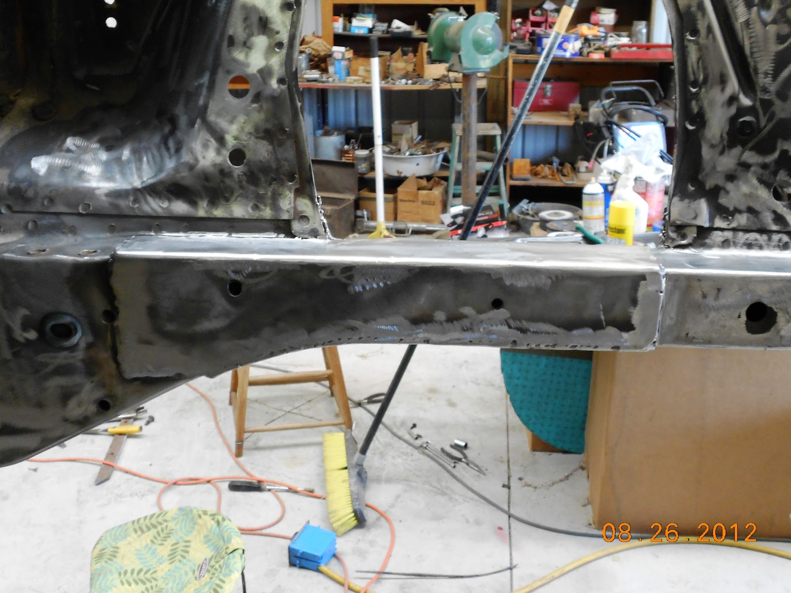
Driver's side frame rail.
 

Wider shot after all pans were cut out.  You might notice something else going on as well that is a teaser about some of the future work.